
Low power mode support for FreeRTOS and TI MSP430FR5739

Overview
After working with the tickless mode using Renesas board, I started to think would it be possible to use tickless mode also with the MSP430. The first question that came to my mind was how to measure current consumption from that MSP-TS430RHA40A board. I downloaded the schematics and had a look. Jumper JP1 can be used to select external power supply. That power supply could be used to measure the current. Unfortunately I don't have such power supply for now. I will still try to make necessary code changes for the tickless mode.
MCU low power modes
MSP430 has low power modes LMP0 through LPM4. These modes has a small differences which clocks are disabled during the low power mode. Wakeup from these modes is possible through all enabled interrupts. And because the control of these modes is through the Status Register (SR), program flow can return previous operating mode if SR content is not changed. Low power modes LPM3.5 and LPM4.5 will also disable voltage regulator in addition to clocks. Wakeup from these modes is more difficult and is possible only through some specific sources like resets.
Implementation
Because I use Digitally Controlled Oscillator (DCO) and ACLK clock for the timers I need to use LPM2 mode where DCO can still source ACLK during low power mode. My demo application is using 16-bit timers with quite fast clock source. This doesn’t matter, but I cannot sleep as long as I could or at least FreeRTOS is expecting which means I won’t get the full benefit of this tickless mode. I started by defining some constants.
Here is my clock system setup function, function to setup RTOS tick timer and function to setup wake up timer which compare register value will be written before every start.
I configured timer A1 to wake up MCU from the tickless mode after the specified time because I don’t want to reconfigure my RTOS tick timer every time this function gets called. We will also use different mode with this timer to be able to read the timer value before it wraps to zero. After adding the new timer I needed to add also new Interrupt Service Routine (ISR) for that timer. As that will be called only after waking up from the tickless mode ISR will make sure that all low power bits are cleared and interrupts are disabled (GIE=0) in SR, interrupts will be enabled at the end of vApplicationSleep function:
Then I configured FreeRTOSConfig.h to take tickless mode into use and added a macro to define function name to be called:
And finally I added function implementation for the tickless mode function:
I also removed idle hook by setting configUSE_IDLE_HOOK to zero and removing vApplicationIdleHook function. There is no point of using that if I want to use tickless mode instead.
Debugging
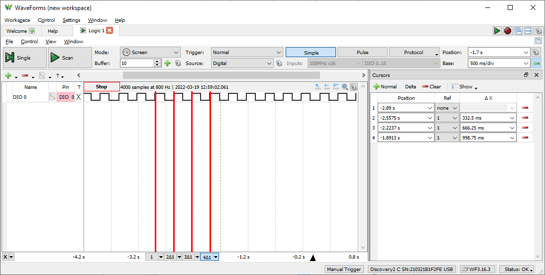
Now I was able to build the demo and start testing. First I wanted to verify if timings were still correct when sleeping between flashing the LED. After connecting my logic analysator, I noticed that the LED was flashing quite close to every 333 ms as expected.
Conclusion
Unfortunately, I didn't have proper equippment to measure the current consumption after enabling the tickless mode. It was easy to configure FreeRTOS tickless mode on, not so easy as with Renesas FSP, but easy anyway.