
Low power mode support for FreeRTOS and EK-RA6M4 board

Overview
Usually it is a good design to minimize embedded system power consumption. By default, many FreeRTOS demo applications set microcontroller (MCU) in to a low power mode in FreeRTOS idle task hook function. However, RTOS tick timer still needs to wake up MCU periodically to handle RTOS ticks which reduces the benefit of going in to the low power mode. The FreeRTOS provides similar mechanism as many other operating systems to help with this issue, tickless idle mode. In this mode, MCU remains in deep power saving state as long as possible by having tick timer interrupt disabled. Some other interrupt will wake up the MCU when necessary and then MCU must adjust RTOS tick count according to the time spend on low power mode to keep everything running correctly when tick interrupt is enabled again. Tickless mode can be enabled in FreeRTOSConfig.h with configUSE_TICKLESS_IDLE. Developer have to implement a portSUPPRESS_TICKS_AND_SLEEP() macro which will be called by the kernel when certain conditions are fulfilled and low power mode is enabled.
MCU low power modes
RA6M4 contains the following low power modes:
- Sleep mode
- Software Standby mode
- Snooze mode
- Deep Software Standby mode
If SBYCR.SSBY bit is zero when WFI instruction is issued, MCU enters to the sleep mode, otherwise it will enter to software standby mode. Figure 10.1 in RA6M4 User’s Manual shows the mode transitions for the low power modes. The difference between sleep and software standby mode is that with sleep mode peripherals function do not stop where as in software standby mode the most of the peripherals and oscillators stop. In snooze mode, some peripherals modules can operate without waking up the CPU. And finally deep software standby mode can remarkably reduce power consumption but most of the CPU registers and peripheral modules become undefined in this mode.
The most of the module-stop states are set by default to prevent clocking the peripherals to reduce power so user must enable modules before using them. There are also different power control modes. High-speed mode has the highest power consumption and is is the default state after reset. Low-speed mode reduces the power consumption but the flash programming and erasure operations as well as using PLL or PLL2 are prohibited. The lowest power consumption is with the subosc-speed mode but it has even more restrictions than the low-speed mode.
Implementation
With the RA6M4 MCU, I will first try out sleep mode and switching between high and low power control modes. To use tickless idle mode, I will need to learn how to use those lower power modes and how to wake up correctly from those modes. Or so I thought. I started by creating a new project for Renesas with FreeRTOS. After having a look at the thread configuration, I noticed that I can use tickless mode just by selecting it from the configuration and Flexible Software Package (FSP) creates the code to implement portSUPPRESS_TICKS_AND_SLEEP macro in ra/fsp/src/m_freertos_port/port.c. It was almost too easy to start using that tickless mode, I didn’t even know which low power mode was configured to be used. Looking at the generated code it is obvious that the default sleep mode was in use. There was also HAL driver for low power modes (g_lpm0) but that was not used in this project.
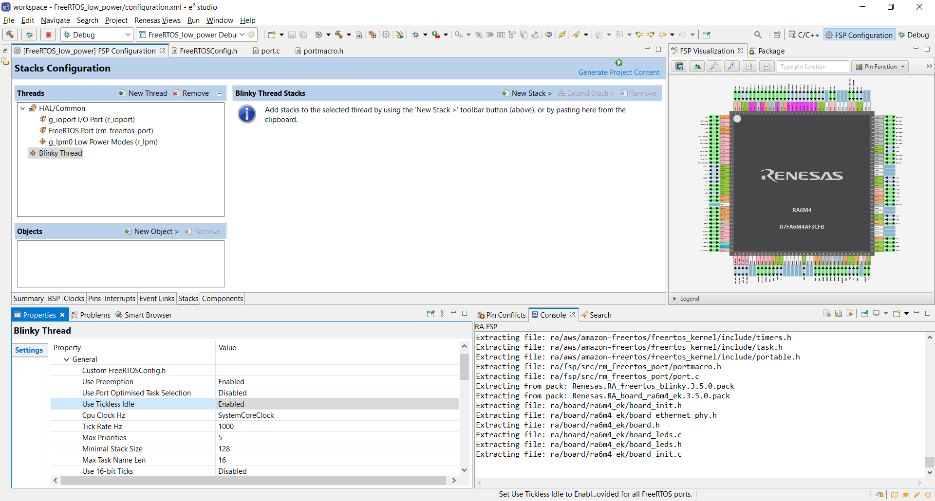
How to measure current consumption to verify the effect of different low power modes? EK-RA6M4 User’s Manual rev 1.01 chapter 7.2 describes the current measurement resistors which can be used to measure MCU USB controller (TP2/TP4) and MCU core (TP1/TP3) power current. I should measure a voltage drop across these resistors and calculate current using Ohm’s law. I will update the results later..