
Getting started with FreeRTOS and TI MSP430FR5739

Overview
FreeRTOS kernel is the "Market leading, de facto standard, and cross platform RTOS kernel". I wanted to get some experience with this RTOS so I decided to try porting one of the MSP430 demo applications to another microcontroller (MCU) variant. I decided to use MSP430 because it is quite trivial to use and I just happen to have one with some tools. The specific variant I have is MSP430FR5739. It has a 16-bit RISC architecture CPU, 16 KB FRAM and 1 KB SRAM. The amount of RAM sounds a bit low. This can be a problem but it should still be feasible. Usually, you would probably use a bare metal application with the MCU like this as its resources are very limited and using RTOS introduces even more overhead.
FreeRTOS repository
To get started, I briefly glanced through the FreeRTOS documentation from their web site and then cloned the primary FreeRTOS distribution with submodules from https://github.com/FreeRTOS/FreeRTOS repository:
After cloning the repository I had the RTOS kernel and several demo applications with MCU ports to be used as a basis for my own application. While browsing through the source code files I found one of the demo application for the MSP430 MCU using Code Composer Studio (CCS) in path Demo\MSP430X_MSP430F5438_CCS. This demo was configured for the MCU variant having much more RAM but it still looked like a good candidate for me -- my goal was to port the demo application for the MSP430FR5739 MCU on the MSP-TS430RHA40A development board from Texas Instruments which has the same architecture.
Porting
Source files
I made a copy of that folder and checked out what was included. There was a text file instructing how this project should be imported to the CCS. There was also a CreateProjectDirectoryStructure.bat batch file which user needs to execute to get all the files copied correctly for the CCS project. After running that batch file, there were many new files copied and I could then import the project to CCS. FreeRTOS documentation suggests to make sure you can build the demo application before starting to modify it. I first tried to build the project but got an error. Root cause for this error was an error directive in FreeRTOSConfig.h configuration file ensuring that CreateProjectDirectoryStructure.bat has been executed before building. After removing that directive I was able to build the project without any errors.
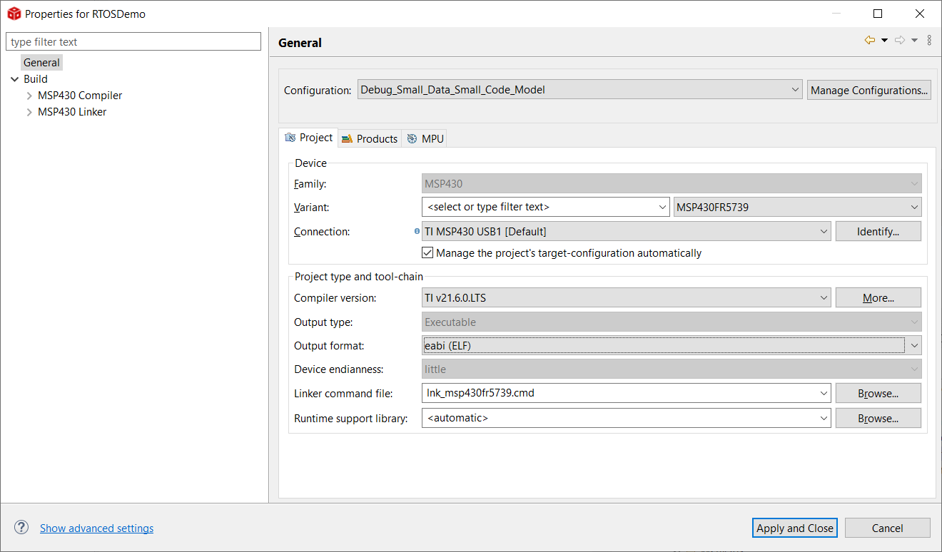
Then after having a look at the port files, I noticed that I didn’t have to modify anything. Stack type and assembly instructions used for stack manipulation are selected based on a data model. I configured both code and data model to “small” using the CCS project build settings. Having small data model means that the MSP430X extended instructions are not used. Extended instructions gives CPU full access to its 20-bit address space. For example, using CALLA instead of CALL would make a subroutine call to a 20-bit address. These differences are handled in data_model.h header file and with some compiler preprocessor directives. While at it, I changed MCU type to the correct one and set output format to Executable and Linkable Format (ELF). Note that you need to fix the MCU type and other settings for all configurations and then select active configuration to be used.
Modifications
Project seemed to include quite many files I wouldn’t need. I investigated the main.c and I could remove most of the demo application code. As I don’t have much RAM I will use only couple of tasks first, one to flash the LED and one for an idle task which will be created when RTOS scheduler is started.
prvSetupHardware function disables the watchdog and setups an internal Digitally Controlled Oscillator (DCO). This MCU clock source has three factory trimmed frequencies to choose from. I will use the high frequency mode with 20 MHz for all ACLK, MCLK and SMCLK clocks. ACLK is further divided by 32 to produce 625 kHz clock for a timer. Demo application was configured to use idle hook which calls vApplicationIdleHook function. This function sets MCU into the LPM3 low power mode. In this mode, only ACLK remains active which means that the RTOS tick timer and UART clock are active even though the MCU is in low power mode. After figuring out the MCU clock frequency, I fixed the configCPU_CLOCK_HZ value in FreeRTOSConfig.h. I was also able to configure RTOS tick timer to timer A0 in vApplicationSetupTimerInterrupt function after configuring the ACLK frequency. Interrupt Service Routine (ISR) for this timer was implemented with vTickISREntry function in port.c file and that did not need any changes.
At this point I removed all unnecessary files from the CCS project, some files for HAL layer for example. File named ParTest.c contains the definitions for the functions accessing the LEDs. The board I was going to use had only one LED so I initialized P1.0 as an output pin and removed all the code related to the LCD. FreeRTOS documentation describes a way how this functionality could be tested. For now, I just initialized the LED on by default and then start toggling it with the task. I needed to add flash module from Demo\Common\Minimal to be able to flash the LED with a task. I modified that module to use 1 LED only. Also some headers were missing so I added those headers and updated include paths for the CCS project.
One more thing to fix was UART functionality in serial.c. This file had initialization for UART and functions for reading and writing characters as well as ISR functions. I needed to fix these settings to build successfully even though I wasn’t planning to use serial module yet.
Testing the modifications
Building and debugging
Now I had everything ready, so I built the code and flash it to the MCU. I was using MSP-FET to flash the firmware to the MCU. I tried debugging the code with the CCS. As suspected at the beginning, amount of RAM makes this a bit difficult. I needed to reduce the heap size, i.e. set configTOTAL_HEAP_SIZE to 500 to be able to build the demo successfully.
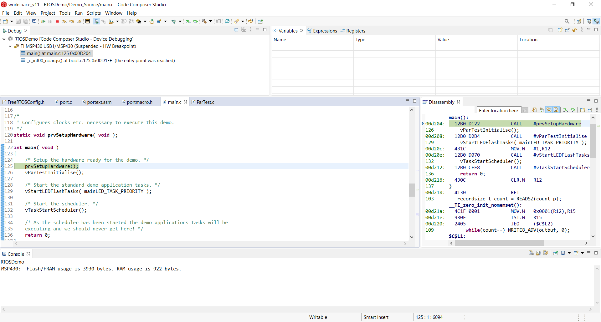
After that I could run the demo, stop to breakpoints and see the LED flashing.
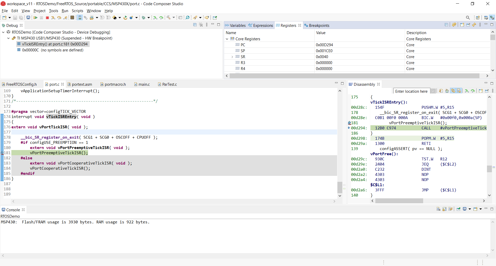
Large data model
I wanted to test large data model also. After switching configuration, I had to again adjust the heap size to be able to run the demo because stack width was increased because of the data model. Once changed, RAM usage was 1024 bytes, i.e. all bytes were in use. So, after setting the large data model and having stack twice as large, made this demo with 2 tasks barely feasible with this MCU with all the RAM memory used.
Timings
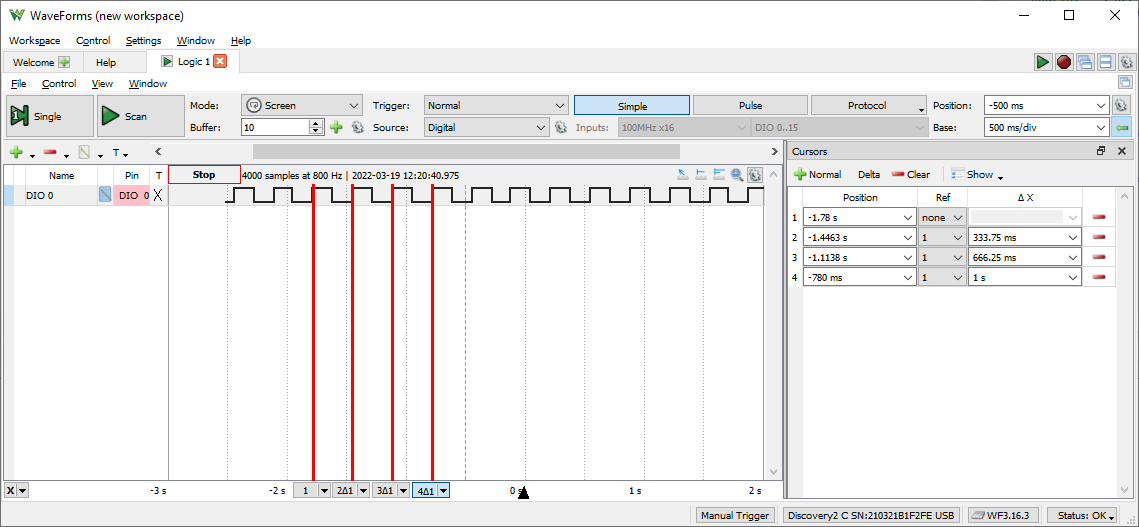
Flash.c defines LED flash rate to be 333 ms. Just by looking at the LED it seemed to be quite close but I wanted to verify this frequency. I connected my Analog Discovery 2 device to the P1.0 pin and measured the pulse. As we can see from the following picture, it is accurate enough for this demo.
Conclusion
As expected already at the beginning, the amount of RAM is not enough to build anything useful with this board. However, FreeRTOS seems to be implementing some ways to reduce memory usage which I might test later. Anyway, it is still possible to run FreeRTOS with such a limited MCU.